Machining
- FYDP Group 35
- Feb 1, 2022
- 2 min read

Updated: Mar 8, 2022
In the week of January 24th, we had received our order from the EMS so we were able to start machining components. The 2 collars and 6 clevises were waterjet with the holes in the correct locations out of the 1/16th aluminium sheet. This could ensure that the holes were in the correct locations and would line up with each other. Then, they were bent to the correct shape. The upper and lower circular plates that form the top and bottom of the housing were also waterjet. This is because they are circular, which is difficult to machine by hand, and the holes needed to be in precise locations so that the brackets, the motor, and the piece that interfaces between the crutch and the housing would all align. The legs were then fabricated by cutting them to length in the bandsaw, and then all of the holes and slots were machined in the mill so that sufficient precision could be achieved. The curvature of some of these parts was achieved using the vertical bandsaw and the belt sander.
By the next week, the machine shop work order had been completed and the housing tube had been picked up from Mr. Metal, so the final components could be fabricated. The housing was created by cutting the 4’’ tube to length on the bandsaw, and then milling out slots for the brackets. Since the holes in the housing plates were very precise, there was sufficient tolerance to drill the housing holes using the drill press to save time rather than in the mill.

Figure 1: Motor Enclosure
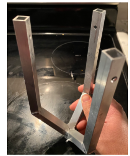
Figure 2: Legs Welded

Figure 3: Power Screw Assembled (Bottom)

Figure 4: Tripod Support Legs Assembled

Figure 5: 3D Printed Parts
Comments