The SELF STANDING CRUTCH
A crutch that is able to automatically stand on its own when not in use, to increase safety and convenience of using crutches
Symposium Day
On March 18th we demonstrated The Self Standing Crutch at the Mechatronics Engineering Capstone Design Symposium. Read more about the event: link

Solution
Our solution entails using a double-collared telescoping tripod for the deployment of the legs actuated using a power screw. Deployment and retraction of the tripod legs will be determined automatically via 3 force sensors and an IMU. A manual mode will also be supported to allow users to have full control over the tripod legs.
Mechanical Design
The system is designed so that the single linear actuator can force the legs both downwards and outwards. It consists of a double collared design with outer and inner support legs connected to each of these collars. The power screw applies force to the upper collar, shown in red (figure 1). Then, the lower collar, shown in green, will hit the hard stop while the upper collar will continue to move downwards, forcing the legs outward. The opposite process happens to retract the legs. The L-shaped block (figure 2) interfaces with the nut on one side and has a bush bearing on the other side that interfaces with a separate shaft that is fixed to the motor housing. This piece serves to constrain the motion of the nut so that it cannot spin, forcing it to move linearly, as desired. The motor housing (figure 3) serves to both support the motor and support the actual crutch leg for when it is in regular use. This motor housing then interfaces with the existing tube of the crutch for the purposes of this prototype.
When the legs are deployed (figure 4), the footprint of the crutch has a 4 inch radius, and the inner supporting legs are at 40 degrees from the vertical. Maintaining a deployed angle below 45 degrees ensures that the legs will not flip inside-out when they are retracted to their undeployed state.

Figure 1: double collared system

Figure 2: L shaped block

Figure 3: Motor housing

Figure 4: Deployed tripod legs on crutch
Electrical Design
A high level diagram of a crutch (figure 5) with the location of the various components. At the top of the crutch is an IMU for orientaiton detection.. On the side of the crutch will be three buttons. One will be used to turn automatic deployment on/off. The second button will be used to force the legs to deploy or retract, based on their current state. The third button will be used to turn the motor on and off to stop idle current draw. The three pressure sensors are placed on the armpit, handle and bottom of the crutch. Based on the state of each sensor, the crutch will deploy, retract or remain the same. Lastly, an electronics box will house the remaining components, including an Arduino Nano, a Buck Converter, Battery and motor controller.
All electronic components will be connected to the arduino board for signal processing (figure 6). The arduino will then send an appropriate signal to the motor controller, which will be connected to the power screw via wires fed through the hollow tubes of the crutch. This signal will stay high until the power screw starts moving in the appropriate direction. It will then transmit its state back to the Arduino for confirmation. If the state is unexpected, the system will be automatically reset to an undeployed state

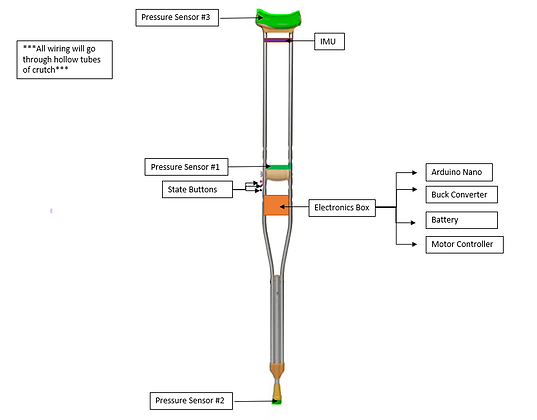
Figure 5: electronics system diagram
Figure 6: electronics prototyping schematic
Background
Based on a study done by the American Physical Therapy Association in 2018, over 1.3 million Canadians depend on either a crutch or cane as their main walking aid due to long term disabilities. However little improvement has been made on the crutch over the years
To dig deeper into this issue, we talked to an amputee. Based on the interview, one major issue individuals face is the inability to easily set crutches aside for short periods of time when not in use. This might seem like a minor issue but becomes very significant when you depend on crutches on a daily basis.
For example, if you simply want a glass of water, you would not be able to just let go of the crutch, but would need to find a way to support the crutch first. In addition, if the crutch falls, picking it back up could be difficult, especially for someone with a disability. Another common use case would be in restaurants. Oftentimes, they would have nowhere to leave the crutch appropriately. In these cases, the server might offer to take the crutch away but that leaves the user with no mobility options.